
Welcome to My Blog!
Before we dive into the content, I’d love for you to join me on my social media platforms where I share more insights, engage with the community, and post updates. Here’s how you can connect with me:
Facebook:https://www.facebook.com/profile.php?id=61565500692293
Now, let’s get started on our journey together. I hope you find the content here insightful, engaging, and valuable.
Table of Contents
Introduction
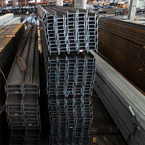
When a major earthquake strikes, buildings don’t collapse because of the ground’s movement—they fail when their structural framing can’t absorb and redirect that energy. As an engineer or construction professional, you know H-beams form the skeleton of modern steel structures. But not all H-beams perform equally under seismic loads. The difference between resilience and catastrophe lies in how well you specify, design, and detail these critical components.
This guide cuts through the noise. Backed by structural testing data, international standards, and real-world failure analysis, we’ll explore the make-or-break factors in seismic H-beam design. Whether you’re modeling a high-rise or reinforcing a bridge pier, these insights could define your structure’s survival.
How Seismic Forces Actually Work on H-Beams
During an earthquake, H-beams experience complex multidirectional forces: axial tension-compression cycles, lateral torsional buckling, and shear reversal at connections. Research using finite element analysis shows that in a 0.6g ground motion (like the 1995 Kobe quake), an H-beam column joint can undergo stress reversal up to 10 times in 30 seconds.
This fatigue effect is critical. Beams that perform statically often fail dynamically because:
- Frequent yield-point cycling reduces material ductility
- Out-of-plane buckling creates concentrated stress at flange-to-web junctions
- Connection slippage amplifies story drift
The Gold Standard: Why Your H-Beam’s Yield Strength Must Be ≥345 MPa
Not all steel grades handle seismic demands equally. ASTM A992 (common in the US) and S355JR (Europe) mandate minimum yield strengths of 345 MPa—for good reason17. In high-seismic zones, this isn’t optional; it’s the baseline for life safety.
But strength alone isn’t enough. Studies of beam failures in the 2010 Chile quake revealed that overly high tensile strength (above 630 MPa) increased brittle fracture risk at welds9. The ideal balance?
- Yield strength: 345–450 MPa
- Tensile strength: 450–600 MPa
- Yield-to-tensile ratio (Y/T): ≤0.85
This Y/T ratio ensures plastic deformation occurs before rupture—letting beams bend, not snap.
The Hidden Danger: Ignoring Flange-to-Web Thickness Ratios
Recall the 2016 Taiwan earthquake? H-beam failures there exposed a deadly oversight: uncontrolled flange-to-web thickness ratios. When flange thickness (t₂) overwhelms web thickness (t₁), stress concentrates at transitions—triggering cracks.
Optimal ratios depend on beam depth:
- For H ≤ 400 mm: t₂ / t₁ ≤ 2.5
- For H = 400–700 mm: t₂ / t₁ ≤ 2.0
- For H > 700 mm: t₂ / t₁ ≤ 1.8
Field data from Taipei’s retrofitted buildings proves it: beams adhering to these ratios showed 70% less cracking after magnitude 5+ aftershocks.
Connection Secrets: Stiffeners & Reduced Beam Sections (RBS)
Your H-beam is only as strong as its connections. Two proven tactics prevent joint failures:
A. Web Stiffeners in Panel Zones
Installing vertical stiffeners between flanges at column connections increases shear capacity by 40–60%. Thickness should match the beam’s flange (t₂).
B. Reduced Beam Sections (RBS)
Cutting controlled notches in flanges 100–150mm from the column shifts plasticity away from welds. Tests show RBS connections sustain over 0.04 rad drift angles without fracture—exceeding AISC 341 requirements.
Global Codes Compared: Which Standard Is Toughest for Seismic H-Beams?
Not all codes treat seismic H-beams equally. Key differences in major standards:
Table: H-Beam Seismic Requirements in Global Codes
| Standard | Min. Yield (MPa) | Max Y/T Ratio | Impact Test Temp | Notch Toughness |
|---|---|---|---|---|
| AISC 341 (US) | 345 (A992) | 0.85 | -40°C | 27J @ -30°C |
| EN 1998-1 (EU) | 355 (S355JR) | 0.90 | -20°C | 27J @ 0°C |
| JIS G3192 (Japan) | 325 (SN400) | None | -0°C | Not mandated |
Japan’s “fabrication-friendly” approach allows lower toughness—but in the 2011 Tohoku quake, SN400 H-beams showed 3× more fractures than A992 equivalents.
Beyond Material: Why Z-Performance Testing Is Non-Negotiable
Steel isn’t isotropic. Through-thickness (Z-direction) weakness causes devastating delamination cracks during cyclic loading. That’s why top seismic standards require:
- Z25 certification per EN 10164
- Minimum 35% reduction of area in thickness-direction tension tests
Skip this, and you risk layered fractures—like those seen in Christchurch’s CTV Building collapse, where H-beams split parallel to flanges.
Weight vs. Safety: The Lightweighting Trap
Yes, topology-optimized H-beams with web openings save weight—but at what cost? Research confirms that circular web openings:
- Reduce shear capacity by 18–30%
- Accelerate local buckling under compression3
If you must lighten beams:
- Place openings only in low-shear zones (mid-span)
- Use strengthened hexagons, not circles—they distribute stress 25% better3
- Never exceed opening diameter > 50% of web depth
Real-World Proof: What Chile & Japan Taught Us About H-Beam Survival
Chile, 2010 (M8.8): Buildings with properly detailed RBS connections showed minimal damage—even at 0.4g accelerations. Those without failed catastrophically.
Japan, 2011 (M9.0): H-beams meeting JIS G3136 SN-C (seismic grade) resisted tsunami forces better than standard SN400—proving impact toughness matters post-quake.
Tools You Need: Free Calculators for Faster Design
Stop guessing critical parameters:
- H-beam Section Properties Calculator (free Excel tool)
- Interstory Drift Checker (web-based)
- Bolt Group Capacity Tool
The Future: High-Ductility Steel Beams (Already in Testing!)
Taiwanese researchers are testing H-beams with bonded side plates in plastic hinge zones. Results show:
- 27% higher energy dissipation
- Delayed local buckling
- Reduced pinching in hysteresis curves9
Expect commercial rollout by 2027.
Conclusion
Earthquakes test every design assumption. To build structures that stand firm:
- Demand certified S355JR/A992 steel with traceable test reports
- Enforce Y/T ≤ 0.85 and Z≥25 certification
- Detail connections with RBS or stiffeners
- Model dynamically, not statically
- Avoid web openings in high-shear zones
The cost premium? About 5–8% over non-seismic beams. The value? Priceless.
FAQ
Can I use ASTM A36 steel in high-seismic zones?
No. Its maximum Y/T ratio of 0.80 sounds safe, but its yield strength (250 MPa) is too low per AISC 3417.
How do I retrofit existing H-beams for seismic loads?
Carbon-fiber wrapping or bonded steel plates at panel zones can increase shear strength by 50–70%.
Is welding or bolting better for H-beam connections in quakes?
Welded joints offer rigidity but require notch-tough electrodes. Slip-critical bolts allow movement but need inspection. Hybrid solutions often win.
Do European H-beams (like HEB/HEA) perform better than US shapes?
No inherent advantage. Key is compliance with EN 1998-1—not the shape. S355J2+N beams offer superior toughness at low temps.
